My RUT955 (RUT9XX_R_00.06.09.5 legacy, connected to RMS) is powered via the 12v circuit of the utility battery in my vehicle (it is directly connected via the power socket pinout). This utility battery is getting power from a solar panel on the roof and whenever I drive the vehicle. Since the solar power alone is not sufficient to power the battery long term, the 12v circuit will eventually break down if I am not driving the vehicle for a longer period. Subsequently, my RUT955 which is essential for the vehicle’s remote security/surveillance goes offline.
I know this question has been asked several times already, but I can simply not make any sense of the responses and conversations that followed them:
How can I remotely monitor the power circuit the RUT955 is connected to and depends on, so I can observe or record the declining voltage over time and can act accordingly to avoid outages? If the device cannot meassure the incoming voltage of the power socket cable and additional cables have to be connected to the input/output pins, I need an easy explanation how to achieve that as I do not understand the complex explanation of the documentation. I also need to know where I can purchase the cable connectors that fit into the input/output sockets of the device.
Additionally, I would like to monitor the incoming power received from the solar panels in order to have a better overview of the current power levels on board.
Yes, I did. But apparently not all of the commands mentioned in the thread. While most of them lead to some error or “command not found”(e.g. “gmsctl -A AT+QADC=0” as mentioned in the first reply), “gsmctl -A ‘AT+ADCREAD=0’” currently prints “+QADC: 1,866”. The number is fluctuating slightly with every subsequent command.
This number might have something to do with the voltage if it is displayed in some special decimal way (the current voltage should be between 10-12v). Trying to understand what the"-A" auxiliary option of gsmctl combined with the AT command exactly does lead me to this wiki page that lists all possible options - none of them has anything to do with voltage, so the number might as well be related to signal strength or something, which would be confusing since the thread was indeed about voltage.
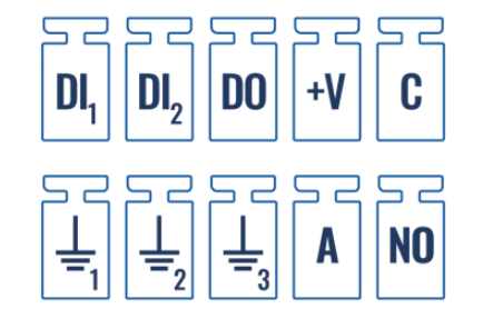
Exacty. Which puts me right back to my original question. How exactly do I use analog input 6 and 9? I simply do not understand the wiki entry. Is it possible to explain this in 2-3 simple sentences?
Example: If you want to measure the voltage of the car battery, you need to connect a “+” cable to pin 6 and a “-” cable to pin 9 by using the pin connector adapter XY. Then go into the Teltonika settings and do YZ.
I really would like to avoid employing yet another device for this setup for something that is so straightforward. TBH, it would be absolutely normal for me if the voltage of its power supply would be displayed on the first page of the router frontend. Especially considering the many (!) different metrics the portal allows to monitor.
So where and when does a router stop being a router (by definition)? With a solar panel then typically a regulator is required so it really wouldn’t be yet another device? Maybe a different device? Internet based.
Of course there is a regulator between the solar panel and the battery. It doesn’t have any network features though. But measuring solar is really secondary - primarily I want to measure the voltage of the power circuit the RUT is powered with.
Could you please at least point me at some information on how to connect my car battery to the input/output sockets? Obviously I cannot just stick cables in there, there must be some connector or cable plug I can purchase, similar how I was able to do it with the power connector.
Look at the Teltonika accessories (google is your friend) … you will find they sell a terminal block connected to the correct plug, or make your own up.
Thats not true. I did Google of course and only found these:
There is no information about whether these connectors are actually supposed to be connected to “normal” cables I can lead to the battery. I mean, there doesn’t seem to be a clamp mechanism that would hold the cable.
I am still hopefull someone who is using their RUT in a similar setup might come accross this thread. I am very sure this can be easily explained with a few simple instructions!
You can use a 4 way screw terminal to connect the pins of the battery to the analog pins of RUT55. Positive Pin of battery to pin9 and common ground pin to pin 6.
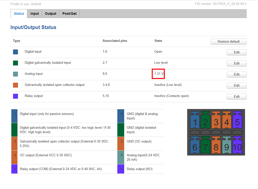
Once connected, you should be able to read your battery voltage level under Services → Input/Output → Status.
Then, go to I/O Juggler, create an Action (HTTP/MQTT). Then in General, select Analog and set the parameters when the Action will be triggered. If you want to constantly send your Battery level voltage in a period/interval, you can enable Modbus and Data to Server feature.
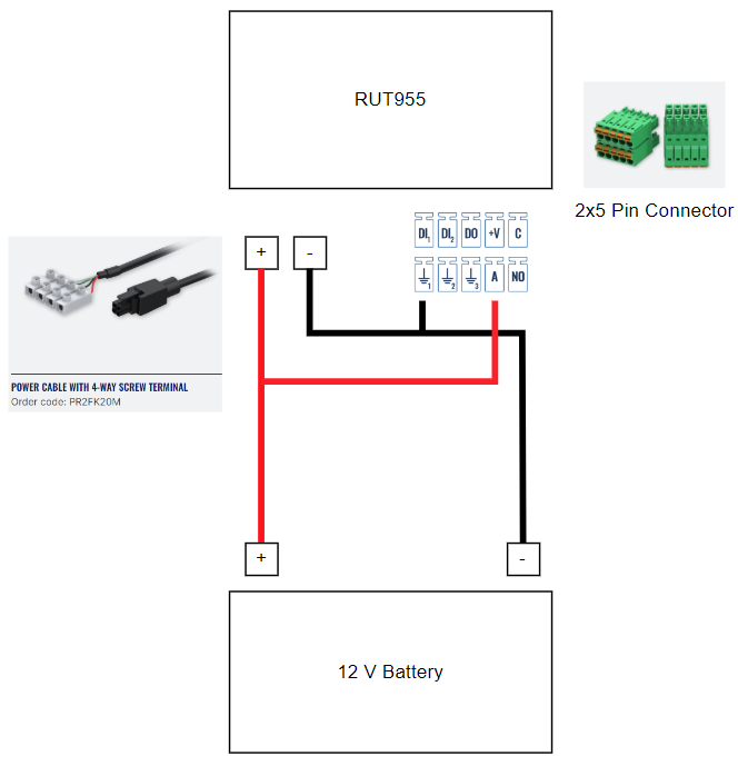
@Janmiguel Thank you so much for your reply! I have already purchased a 4 way screw terminal before. This connector does not fit with the input/output ports on the RUT955, which is where my confusion comes from. Please have a look:
@Janmiguel To add to the confusion I just noticed this when following your steps: On the " Input/Output Status" page is a list of associated pins and their status. The analogue input for associated pins 9 and 6 actually already reports a “state” even though these pins are not connected. While the number is very off obviously, it seems to be a live value as it slightly fluctuates between 30 and 35 V:
The 4 way terminal is used on the power terminal to easily connect battery lines to power pins of RUT955 and I/O terminal. There is another accessory for I/O terminal which is 2x5 Pin connector. Is it included in the packaging?
This is should not be the case as nothing is still connected to it. I’ve observed that you have a fairly old firmware. Can you upgrade it to the latest firmware version? You might encounter a different result. Kindly use this link as a guide for firmware upgrade.