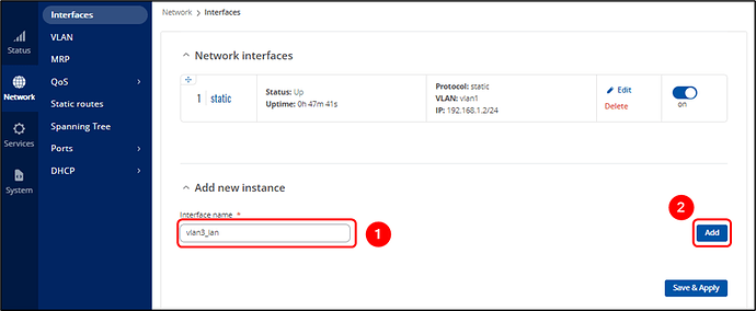
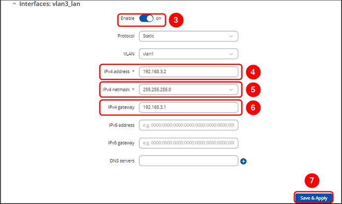
Sorry if I caused any confusion, but you’re almost there! I made a mistake in the picture between steps 3 and 4 when creating the LAN interface—the VLAN was set to vlan1, but it should have been vlan3.
The TSW202 switch can not only remove tags but also add them, acting as a converter between tagged and untagged traffic. VLANs are separate networks identified by their VLAN ID (or tag). Tagged interfaces communicate with tagged devices, while untagged interfaces communicate with untagged devices.
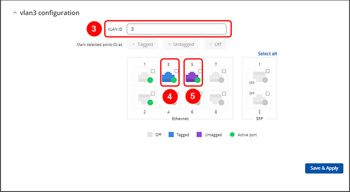
If you connect a device with a tagged VLAN to the TSW202 switch, and the port is configured with the appropriate VLAN ID, it will communicate with the device. If another port is set as untagged for the same VLAN, devices connected to it will also be able to communicate. The switch handles the conversion by adding or removing the VLAN tag based on the traffic’s direction. This allows both tagged and untagged interfaces to coexist within the same VLAN, enabling devices connected to those interfaces to communicate with each other, regardless of whether they are using tagged or untagged traffic.
Importantly, the switch itself must also be part of the VLAN. This requires configuring the switch’s LAN interface for that VLAN.
Summary:
- Configure both tagged and untagged ports for the same VLAN ID (e.g., VLAN 3).
- Set up the switch’s LAN interface to communicate within the tagged VLAN network.
- Connect tagged devices to the tagged port and untagged devices to the untagged port.
In your particular scenario, I imagine everything should look like this:
VLAN 10
Network IP : 192.168.1.0
Mask : 255.255.255.0
Router’s IP (Gateway) : 192.168.1.1
VLAN ID/Tag: 10
Now, I assume this network is configured as a tagged VLAN, meaning the router will only communicate with devices that tag their traffic and have IP settings corresponding to this VLAN.
To set this up on the TSW202:
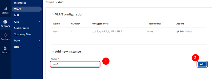
Create a new VLAN (follow the first two images from my example) with the ID “vlan10” and enter “10” in the VLAN ID section. Set one port as tagged (for connecting your tagged VLAN Draytek router) and another as untagged (for connecting your Draytek switch).
Create a new LAN interface with settings that match the VLAN configuration on your tagged VLAN router (refer to the third and fourth images from my example, ensuring you select “vlan10” instead of “vlan1”).
For your Draytek AP906 access point, I assume you’re connecting one of its LAN ports to the Draytek switch. However, the AP906 still needs to be configured to operate within the same VLAN network, without tagging. To do this, adjust its LAN settings to match the VLAN network settings with static IP, but without applying any tags.
Additionally, if your Draytek router is the DHCP server, you must turn off the DHCP server on the AP906. Only one DHCP server can be active on the network at a time, otherwise there might be a conflict. By doing this, the AP906 will function solely as a relay for DHCP settings to the connected devices.
The same procedure applies to any VLAN, including vlan1.
Please try configuring the network accordingly and let me know if everything works as expected.
Kind regards,
Lukas


