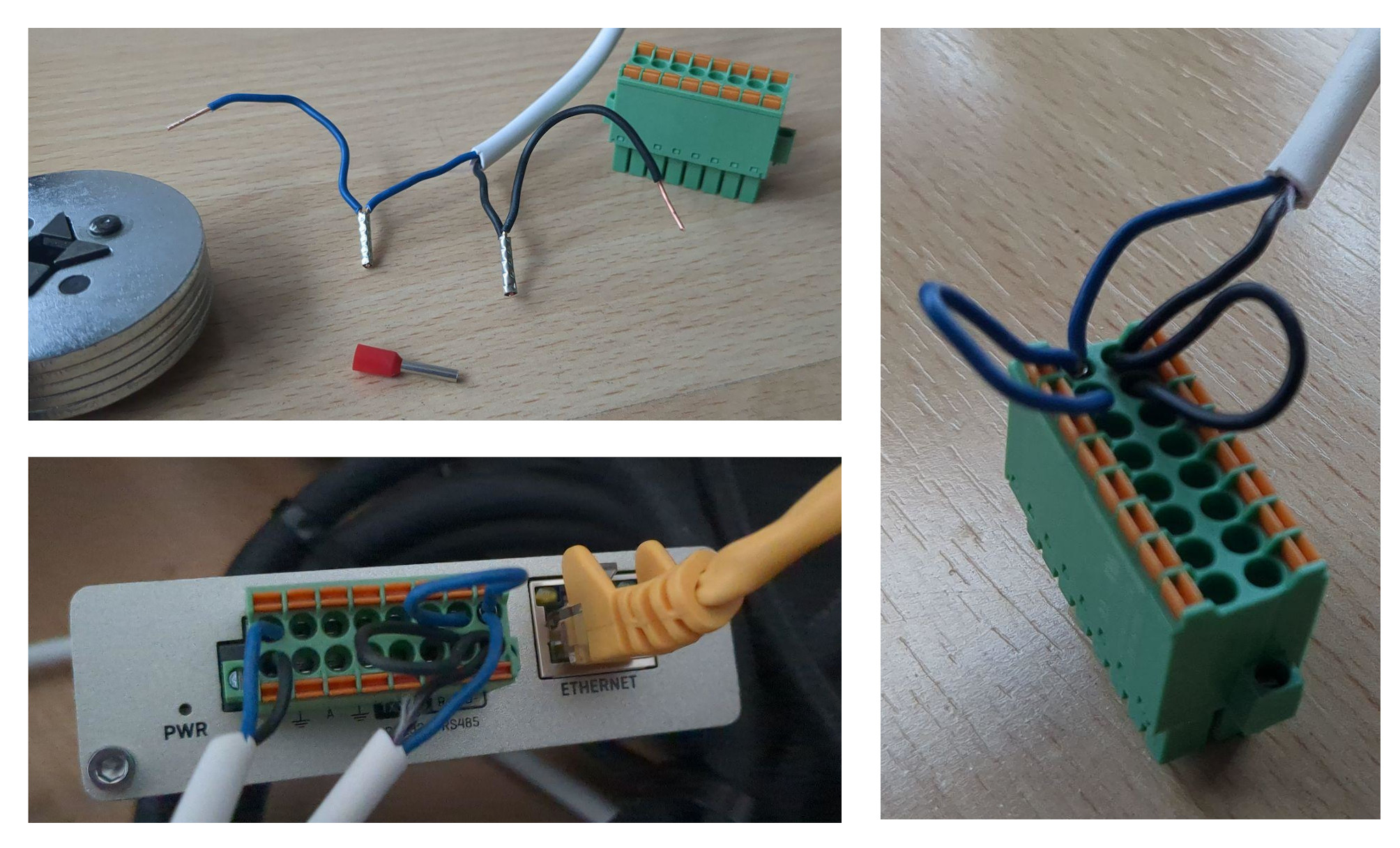
After hours of troubleshooting, here is the solution for our case: wire ferrules!
Goal
RS485 connection between a battery and a TRB245 (TRB2_R_00.07.14.4) in order to be able to send Modbus RTU commands.
Environment
- The battery has two jacks, A and B, and no extra ground connection.
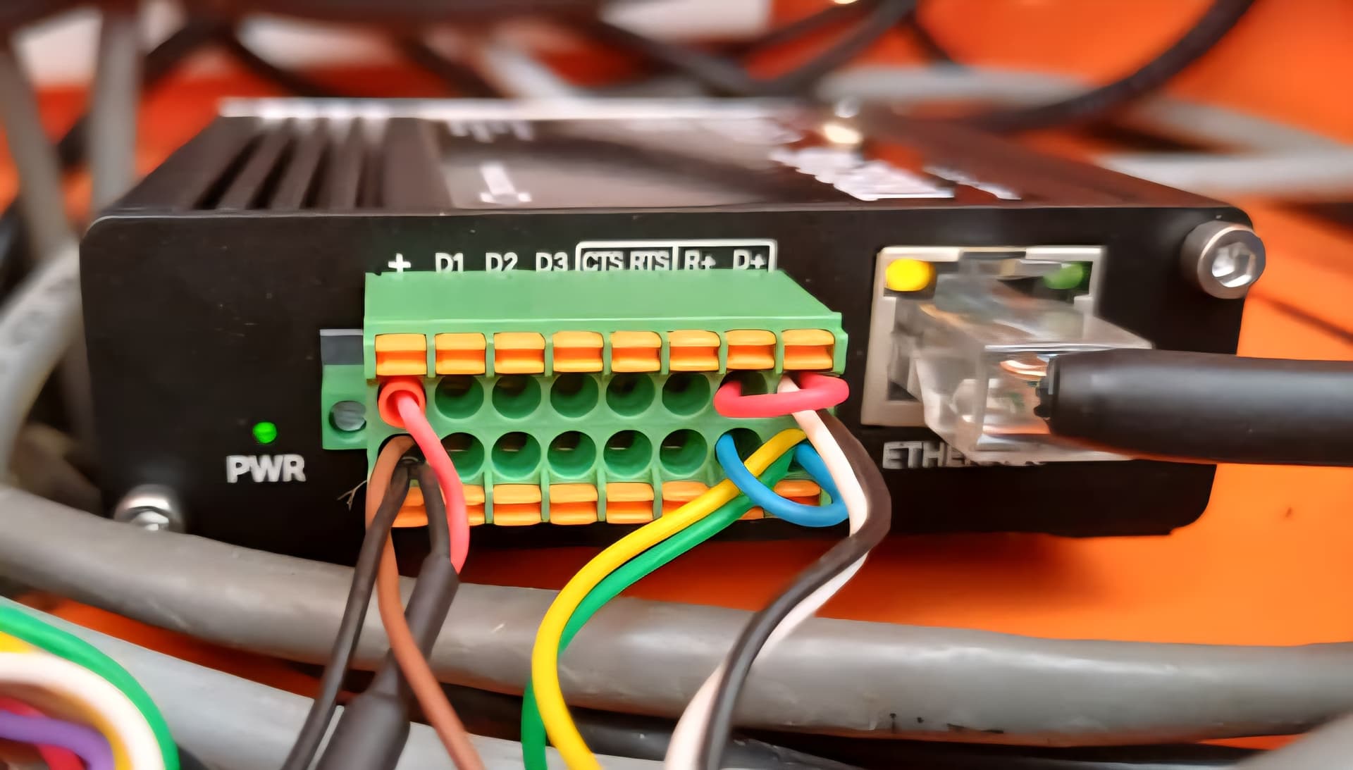
- The TRB245 has D+, D-, R+, and R-, using the green Combicon (Phoenix Contact 1790357) to connect.
- A YR 2x0.8 mm serial cable with rigid ends and no shielding is used. It is only 30-50 cm.
The cable length is very short in this case. We therefore do NOT need the following:
- Shielded cable.
- 120 ohm resistor.
- Extra ground connection.
Three new TRB245 were used in the tests. All exhibited the same behavior.
Wiring:
- Connect A/B (battery) to D+/D- (TRB245). Test whether the connection is correct (see below), otherwise swap.
- USE WIRE SLEEVES to additionally bridge D+ to R+ and D- to R-.
The critical aspect are the ferrules: without them, it was not possible to establish a stable connection! This means that simply plugging the rigid ends into the Phoenix block (almost) always leads to (sometimes) faulty transmission!
Below you find the log of failures…
Software
All Serial/Modbus services must be deactivated in the WebUI for the following test. For example, no Services/Modbus/Modbus-Serial-Client may be activated. Ideally, perform a factory reset to start from scratch.
In the WebUI, under Services/Modbus/Modbus-Serial-Client, you have the option to test the serial connection. But it is much faster to perform this test via the console using the equivalent ubus call command:
# get ubus object name
$ ubus list | fgrep -i client
modbus_client.rpc

# list expected object parameters
$ ubus -v list modbus_client.rpc
  ... "serial.test": "id":"Integer","timeout":"Integer","function":"Integer","first_reg":"Integer","reg_count":"String","data_type":"String","no_brackets":"Integer","serial_type":"String","baudrate":"Integer","databits":"Integer","stopbits":"Integer","parity":"String","flowcontrol":"String"} ...

# check available TRB245 parameters
$ cat /etc/board.json
...
    "serial": [
      ...
        "devices": [
          "rs485"
        ],
        ...
...
FYI, some troubleshooting when you run ubus call because it prints very misleading error messages:
# id with wrong type, should be int
$ ubus call modbus_client.rpc serial.test '{"id": "1"}'
{
	"error": 2,
	"result": "Missing id"
}
# -> missing can also be wrong type (string vs int in this case)
In the following, we always use this command:
$ ubus call modbus_client.rpc serial.test '{ "id": 1, "timeout": 2, "function": 4, "first_reg": 4663, "reg_count": "1", "data_type": "hex", "no_brackets": 0, "serial_type": "/dev/rs485", "baudrate": 115200, "databits": 8, "stopbits": 1, "parity": "none", "flowcontrol": "none" }'
Log of Failures
All tests and settings can be carried out without restarts/reboots. Simply adjust the cabling and execute the ubus call command. However, it is important for understanding to always execute it several times (fast, slow) in succession. You will then see that incorrect (unstable) wiring does not produce a consistent picture, but rather different results:
Serial opposite (battery) not connected
$ ubus call modbus_client.rpc serial.test <json>

{
	"error": -1,
	"result": "Failed to get response: Operation timed out"
}
D+ and D- swapped (and no bridge to R+/R-)
$ ubus call modbus_client.rpc serial.test <json>

# mostly
{
	"error": -1,
	"result": "Failed to get response: Invalid CRC"
}

# but also
{
	"error": -1,
	"result": "Failed to get response: Response not from requested slave"
}
D+ and D- correct, but no bridges to R+/R-
$ ubus call modbus_client.rpc serial.test <json>

{
	"error": -1,
	"result": "Failed to get response: Operation timed out"
}
D+ and D- correct, but only one bridge (to R+ or to R-) connected
$ ubus call modbus_client.rpc serial.test <json>

# mostly
{
	"error": -1,
	"result": "Failed to get response: Invalid CRC"
}

# but also
{
	"error": -1,
	"result": "Failed to get response: Response not from requested slave"
}

# or
{
	"error": -1,
	"result": "Failed to get response: Invalid data"
}

# and rarely (but unreliably) it also works
{
	"error": 0,
	"result": "\"001A\""
}
D+ and D- correctly and bridges from D+ to R+ and D- to R-
$ ubus call modbus_client.rpc serial.test <json>

# works
{
	"error": 0,
	"result": "\"001A\""
}
Works - but ONLY reliably if D+/R+ and D-/R- are each connected with wire ferrules. Simply plugging them in did not produce reliable results, but almost always resulted in errors.
At Teltonika
(1) If these explanations are helpful, they could perhaps also be linked here.
(2) ubus call commands save a lot of time during debugging compared to using the WebUI. However, finding the right parameters is tedious and time-consuming. Therefore, it would be very helpful if there were comprehensive ubus call documentation/API specs. Is this the case, and have I overlooked it (in the wiki)?
Best regards, Simon