TRB246 get Modbus data from slave

Hi,
I recently purchased a solar charge controller (Epever Tracer 3906BP) which has a Modbus RTU port that can be used to get data (battery voltage, solar panels voltage, etc) from the device.
On the documentation of the solar charge controller I read:

  1. The default controller ID number is “1”, we can modify the ID via PC common software
  2. Serial communication parameters: baud rate 115200, data bits 8, stop bits 1, no data flow control.
  3. Register address uses hexadecimal format, the base address offset is 0x00
  4. All 32-bit-length data uses two 16-bit registers to represent (L and H register, respectively), for example, the value of the array rated power is 3000, data multiple is 100, the data of L register (address 0x3002) is 0x93E0 and the data of H register (address 0x3003) is 0x0004.

I have connected the Epever to a RPi via a FTDI chip (RS485 to USB) and I am able to get data (battery voltage in the example below) from it via a simple C++ software:

uint8_t* cmd = {0x01, 0x04, 0x33, 0x1a, 0x00, 0x01 };
uint16_t crc = ModRTU_CRC(cmd, 6);
uint8_t crc_a = (uint8_t)(crc >> 8);
uint8_t crc_b = (uint8_t)(crc);
uint8_t buffer[8];
buffer[0] = cmd[0];
buffer[1] = cmd[1];
buffer[2] = cmd[2];
buffer[3] = cmd[3];
buffer[4] = cmd[4];
buffer[5] = cmd[5];
buffer[6] = crc_a;
buffer[7] = crc_b;
//for (int i = 0; i < 8; i++){debug("Writing 0x%02X ", buffer[i]);}
size_t size = 8;
m_uart->flush();
m_uart->write(buffer,size);
Counter<float> timer(1.0);
int index = 0;
uint8_t bfr[255];
uint16_t val = 0;
while (!timer.overflow() && index < size-1)
{
if (!Poll::poll(*m_uart, timer.getRemaining()))
break;
size_t bytes_read = m_uart->read(bfr+index, sizeof(bfr));
index +=bytes_read;
print("EPEVER read: %d bytes", bytes_read);
}
if(index == size-1){
val = (uint16_t)bfr[3] << 8 | (uint16_t)bfr[4];
print("EPEVER says: %d, in hex it is 0x%04x", val,val);
}
return val;
}


uint16_t ModRTU_CRC(uint8_t* cmd, int len)
{
  uint16_t crc = 0xFFFF;
  
  for (int pos = 0; pos < len; pos++) {
      crc ^= (uint16_t)cmd[pos];          // XOR byte into least sig. byte of crc
  
      for (int i = 8; i != 0; i--) {    // Loop over each bit
      if ((crc & 0x0001) != 0) {      // If the LSB is set
          crc >>= 1;                    // Shift right and XOR 0xA001
          crc ^= 0xA001;
      }
      else                            // Else LSB is not set
          crc >>= 1;                    // Just shift right
      }
  }
  // Note, this number has low and high bytes swapped, so use it accordingly (or swap bytes)
  crc = (crc >> 8) | (crc << 8); // endiannes
  return crc;  
}

With that code I am able to get data from the device. The returned ‘val’ is a uint16_t that I then cast to double.

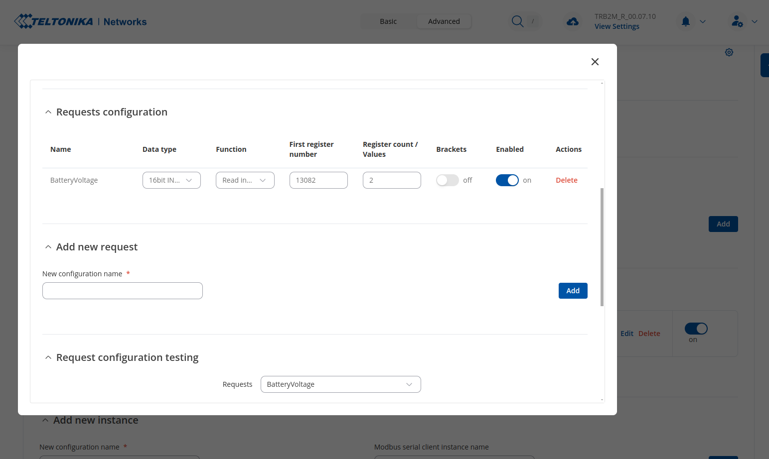
I would like to do the same with a TRB246 that I recently purchased.
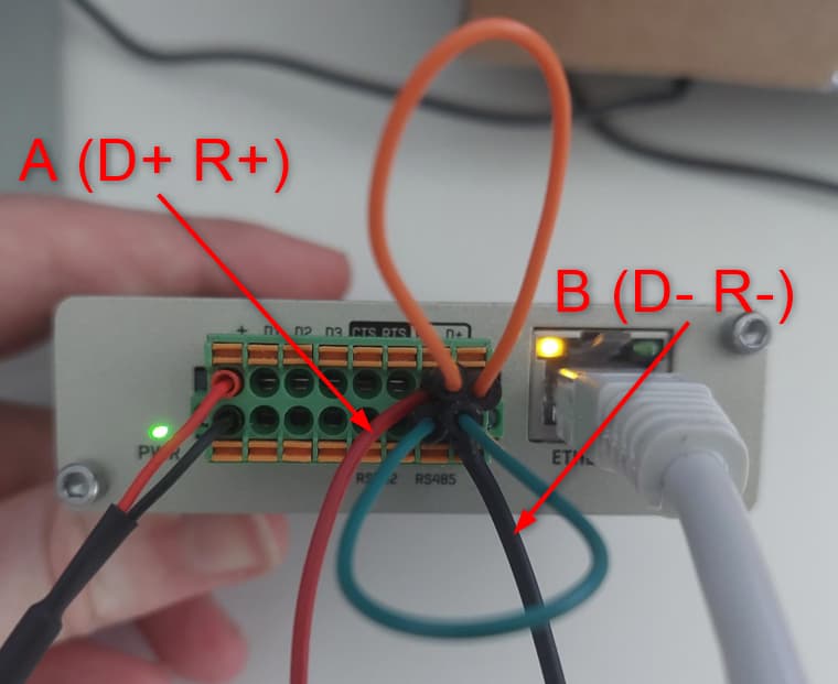
I have connected the Epever wire A to TRB246 D+ and Epever wire B to TRB246 D-.

Could you please guide me on the setup of Modbus RTU on the TRB246 side? I assume that the TRB246 should act as master in the Modbus network and that from it I should be able to poll data from the Epever, same was as I do with the RPi.

Could you please help with this configuration and if there is some quick script or tool that I can use via CLI on the TRB246 to check the electrical connection and then retrieve some data via Modbus? I was thinking about making a bash script, but not sure that is ideal.

Thank you,
Alberto

Hello,

Thank you for your inquiry. Based on your description, it seems that the wiring should be correct.

To configure the TRB246 as a Modbus RTU master, you can do this through the WebUI by following these steps:

  1. Log into the WebUI and navigate to: Services → Modbus → Modbus Serial Client.
  2. Click on the “Add” button, provide a name for the new instance, and select the RS485 interface as the communication port.
  3. In the newly opened Modbus client configuration window, specify the necessary parameters (baud rate, data bits etc.) according to your solar charge controller’s requirements.
  4. Scroll down to the Request Configuration section, where you will define how the data should be read from the Epever device. For each register you want to read:
  • Specify a name for the request.
  • Select the Data type (e.g., 16-bit, 32-bit).
  • Choose the Function (e.g., read holding registers).
  • Specify the First register in decimal format (you can refer to the Modbus documentation for the correct register addresses).
  • Enter the Register count to define how many registers you want to read.
  1. Once the configuration is complete, enable the request and use the Request configuration testing section to test if the TRB246 is successfully communicating with the Epever device and retrieving the data.

For further details and to ensure you have the latest information on setting up the Modbus Serial Client on the TRB246, you can also refer to the official documentation here:
TRB246 Modbus Serial Client Setup Guide

If you need any additional assistance or run into any issues, feel free to reach out. I’ll be happy to help.

Best regards,

Hi Martynas,
thank you very much for your reply.
I have created a configuration exactly as you specified.

The values from the solar charge controllers are 32-bit data. All 32-bit-length data uses two 16-bit registers to represent (L and H registers, respectively). The documentation specifies that to read (for example) the battery voltage I need to read address 331A (HEX) using function code 4.
So in the Request Configuration I specified 16bit UINT high byte first, function 4, first register 13082 (331A hex) and register count/values 2, brackets off.
See image:

When I click on Test I get: Failed to test request, check your configuration.

I also tried on the command line of the modem:

but this fails with error:
{
“error”: 2,
“result”: “Missing register count”
}
Command failed: Invalid argument

Any idea why this is failing?

Thank you very much,
Alberto

Some more improvement.

By running the command:

root@TRB246:~# ubus -v list modbus_client.rpc
'modbus_client.rpc' @c7d6586c
	"tcp.test":{"id":"Integer","timeout":"Integer","function":"Integer","first_reg":"Integer","reg_count":"String","data_type":"String","no_brackets":"Integer","ip":"String","port":"String","delay":"Integer"}
	"serial.test":{"id":"Integer","timeout":"Integer","function":"Integer","first_reg":"Integer","reg_count":"String","data_type":"String","no_brackets":"Integer","serial_type":"String","baudrate":"Integer","databits":"Integer","stopbits":"Integer","parity":"String","flowcontrol":"String"}
	"clean_connections":{}

I realized my syntax was wrong.
So I tried:

root@TRB246:~# ubus call modbus_client.rpc serial.test '{"id":1, "timeout":10, "function":4, "first_reg":13082, "reg_count":"2", "data_type":"16bit_uint_hi_first", "no_brackets":1, "serial_type":"/dev/rs4
85", "baudrate":115200, "databits":8, "stopbits":1, "parity":"None", "flowcontrol":"None"}'
{
	"error": -1,
	"result": "Failed to get response: Operation timed out"
}

Assuming that integers require no quotes while strings do (no idea that being correct?).

Now I get “Failed to get response: Operations timed out”

I guess this is an improvement.
Any further suggestion?

Thank you,
Alberto

Hi, any kind update here?

Thank you very much,
Alberto

Hello,

Could you please try using the Read holding registers (3) function instead and double-check that the register count and values are correct, as this may help resolve the timeout issue?

If that doesn’t resolve it, try setting the function to Read input coils (2). Additionally, reviewing your controller’s data sheet might provide more relevant information for configuration.

Best regards,

Hi Martynas,
thanks for your support.

Why should I try another function code while the documentation of the controller says the battery voltage should be read using function code 4?
Anyways, thank you for the hints, but unfortunately it did not help.

I wanted to be sure about the cabling and I have connected the charge regulator to a FTDI USB to RS485 chip directly to my laptop (which runs Ubuntu 22.04).
I have made a simple Python script to retrieve the battery voltage:

import serial
import struct

def calculate_crc(data):
    """Calculate ModRTU CRC."""
    crc = 0xFFFF
    for pos in data:
        crc ^= pos
        for _ in range(8):
            if (crc & 0x0001) != 0:
                crc >>= 1
                crc ^= 0xA001
            else:
                crc >>= 1
    return struct.pack('<H', crc)  # Little-endian

def read_battery_voltage(serial_port):
    """Send Modbus request and read battery voltage."""
    unit_id = 1  # Default Modbus ID for Epever
    function_code = 0x04  # Read Input Registers
    start_address = 0x331A
    register_count = 1

    # Build Modbus RTU request
    request = struct.pack('>B B H H', unit_id, function_code, start_address, register_count)
    request += calculate_crc(request)

    try:
        with serial.Serial(serial_port, baudrate=115200, timeout=2) as ser:
            # Flush input and output buffers before sending data
            ser.reset_input_buffer()  # Clear input buffer
            ser.flush()  # Clear output buffer

            # Send request
            ser.write(request)

            # Flush output buffer after sending to ensure clean communication
            ser.flush()

            # Read response (expected length: 7 bytes for this query)
            response = ser.read(7)

            # Validate response length
            if len(response) < 7:
                print(f"Incomplete response: {response}")
                return

            # Validate CRC
            crc_received = response[-2:]
            crc_calculated = calculate_crc(response[:-2])
            if crc_received != crc_calculated:
                print(f"CRC error: received {crc_received.hex()}, expected {crc_calculated.hex()}")
                return

            # Parse battery voltage from response
            if response[1] == function_code:  # Verify function code in response
                raw_value = struct.unpack('>H', response[3:5])[0]
                battery_voltage = raw_value / 100.0  # Scale factor as per documentation
                print(f"Battery Voltage: {battery_voltage:.2f} V")
            else:
                print(f"Unexpected response: {response.hex()}")

            # Flush the input buffer after reading to ensure no stale data remains
            ser.reset_input_buffer()

    except serial.SerialException as e:
        print(f"Serial error: {e}")

# Update with the correct serial port
serial_port = '/dev/ttyUSB0'
read_battery_voltage(serial_port)

This works fine and I am able to print out the voltage.
Is there any hint in the script that makes you doubt about my setup in the TRB246?
What I tried so far is testing the modbus client query via the GUI and also via the CLI with the command:

root@TRB246:~# ubus call modbus_client.rpc serial.test '{"id":1, "timeout":3, "function":4, "first_reg":13082, "reg_count":"2", "data_type":"16bit_uint_hi_first", "no_brackets":1, "serial_type":"/dev/rs48
5", "baudrate":115200, "databits":8, "stopbits":1, "parity":"None", "flowcontrol":"None"}'
{
	"error": -1,
	"result": "Failed to get response: Operation timed out"
}

Please let me know if I can do further tests to help you debug my problem.

Thank you for your time,
Alberto

Hello Alberto,

Thank you for your detailed update.

Could you let us know what specific error appears when you try to read the Modbus server’s (slave’s) register values from the WebUI?

Additionally, if you’re concerned about the cabling setup, could you check or provide a screenshot of your current RS485 connection? Here’s a reference screenshot for how RS485 wiring should look on the TRB246:

Best Regards,

Hi Martynas,
in my setup I did not connect D+ and R+ together, nor D- and R-.

This now works!
Thanks for your time.

Alberto

1 Like

Hello,

Glad to hear it’s working now! Thank you for the update, and don’t hesitate to reach out if you need any further assistance.

Best Regards,

This topic was automatically closed 2 days after the last reply. New replies are no longer allowed.