Then I have connected a 12V+ from a battery on pin 1 of the relay, and a 12VDC device on pin 2 of the relay. The powered device (load) has ground shared with the battery and the modem. When I toggle the relay from the nothing happens, in fact, the load is always powered. It seems like the D1 output has not effect. Same for D2 and D3.
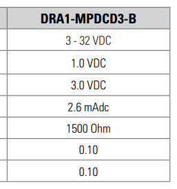
It seems to me that the D1 specs fit well with the requirements to control the relay:
It’s a bit hard to visualise your set up, but I’ve just been doing the similar thing with a TRB255 powering external relays and had what I think is a similar issue. I hadn’t realised the digital outputs are “Open Collector”, which essentially means they complete the circuit to earth for your load when active high. Therefore, if you connect the ground (-) for your load to PIN2 and the 12VDC (+) directly to load perhaps it might work for you. It did for me.
No worries. I’m happy to help out if I can as we’re all learning.
Assuming the relay input is rated for 12VDC, my suggestion would be to remove “GND-to-Input4”, connect “D1-to-Input4”, and connect your 12VDC+ feed (red) to Input3+.
Fit a diode across the relay input is also recommended to prevent back feed from the collapsing field of the input coil, so if your relay doesn’t have one already fitted you might need to check this.