Greetings, @ivju ,
Apologies for a delayed response,
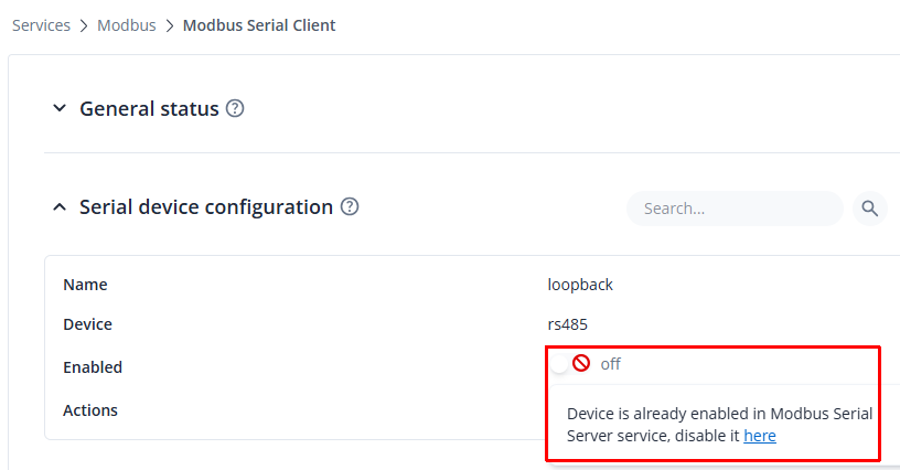
Please disregard the previous information regarding the possibility of using the TRB145 simultaneously as a Modbus Serial Client and Modbus Serial Server on the same RS485 interface. After further testing and verification, we can confirm that this configuration is not supported due to the limitation of the serial interface.
However, the requested functionality can still be achieved by configuring the TRB145 as a Modbus RTU Slave (Server) and using a custom script to monitor the Modbus register value and trigger an SMS notification.
The intended setup would be:
PLC (Modbus RTU Master)
        |
        | RS485 Modbus RTU
        |
TRB145 (Modbus RTU Slave / Server)
        |
        |
Custom script monitors register value
        |
        |
SMS notification
In this configuration:
- The PLC writes values to the TRB145 Modbus register block.
- The TRB145 stores these values in the configured Modbus register file.
- A custom script running on the TRB145 monitors the register value.
- When the predefined condition is met (for example, register value = 1), the script triggers an SMS notification.
Configuration Guide:
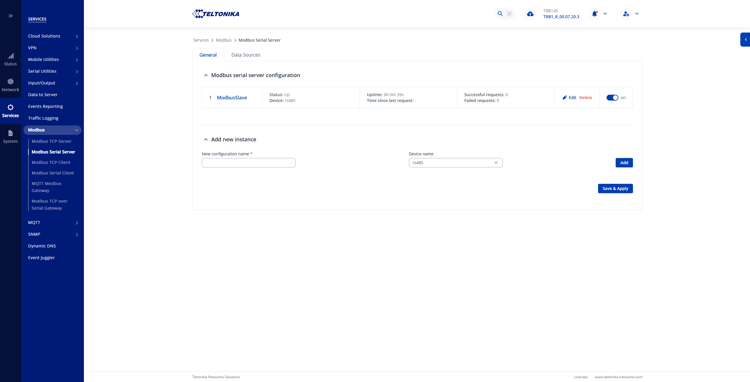
- Configure TRB145 as Modbus RTU Slave
Navigate to:
Services → Modbus → Modbus Serial Server
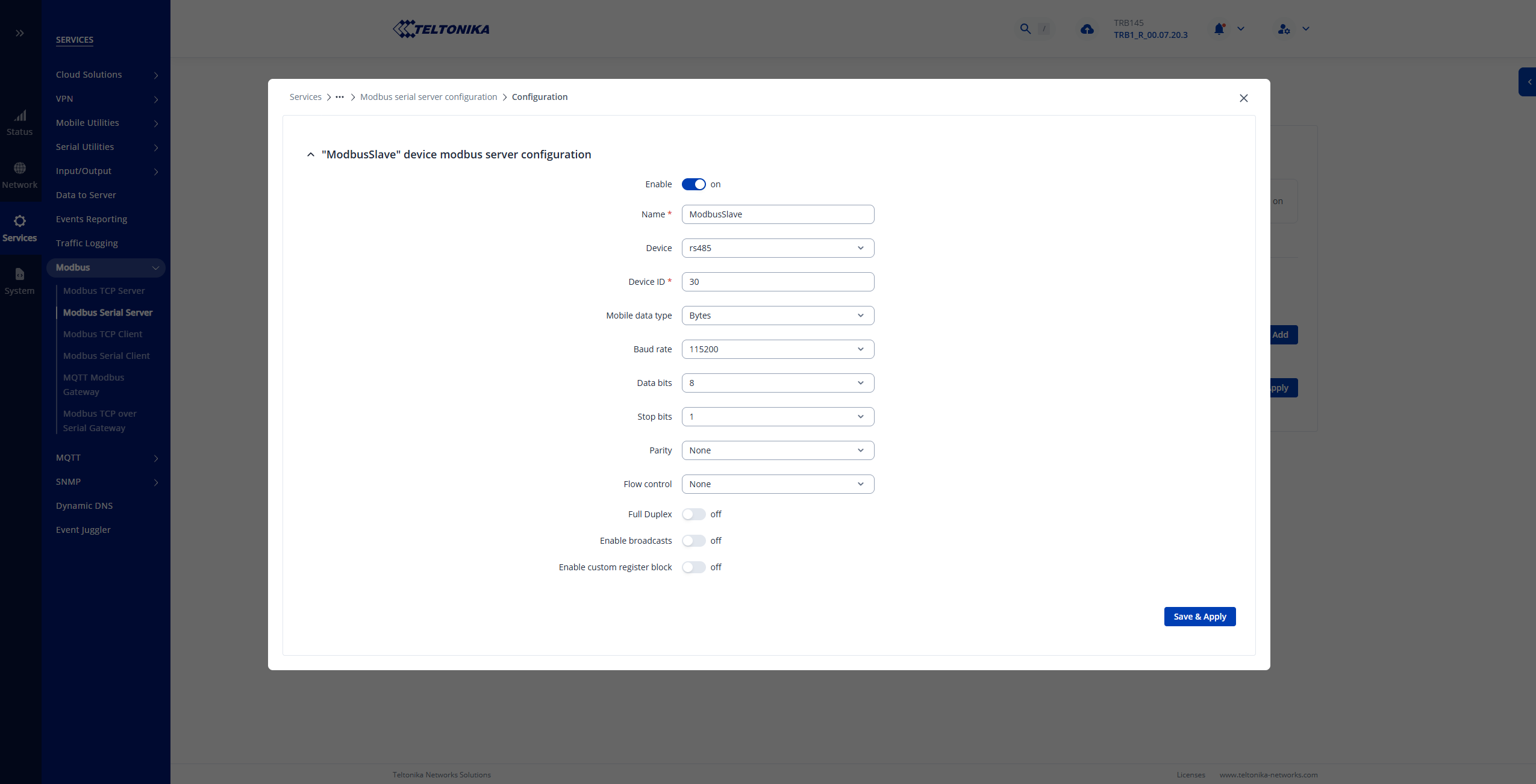
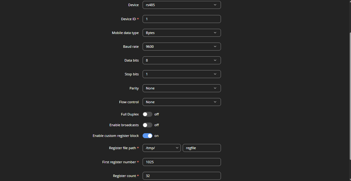
Configure the RS485 Modbus parameters according to the PLC configuration:
- Serial interface: RS485
- Baud rate
- Data bits
- Stop bits
- Parity
- Slave ID
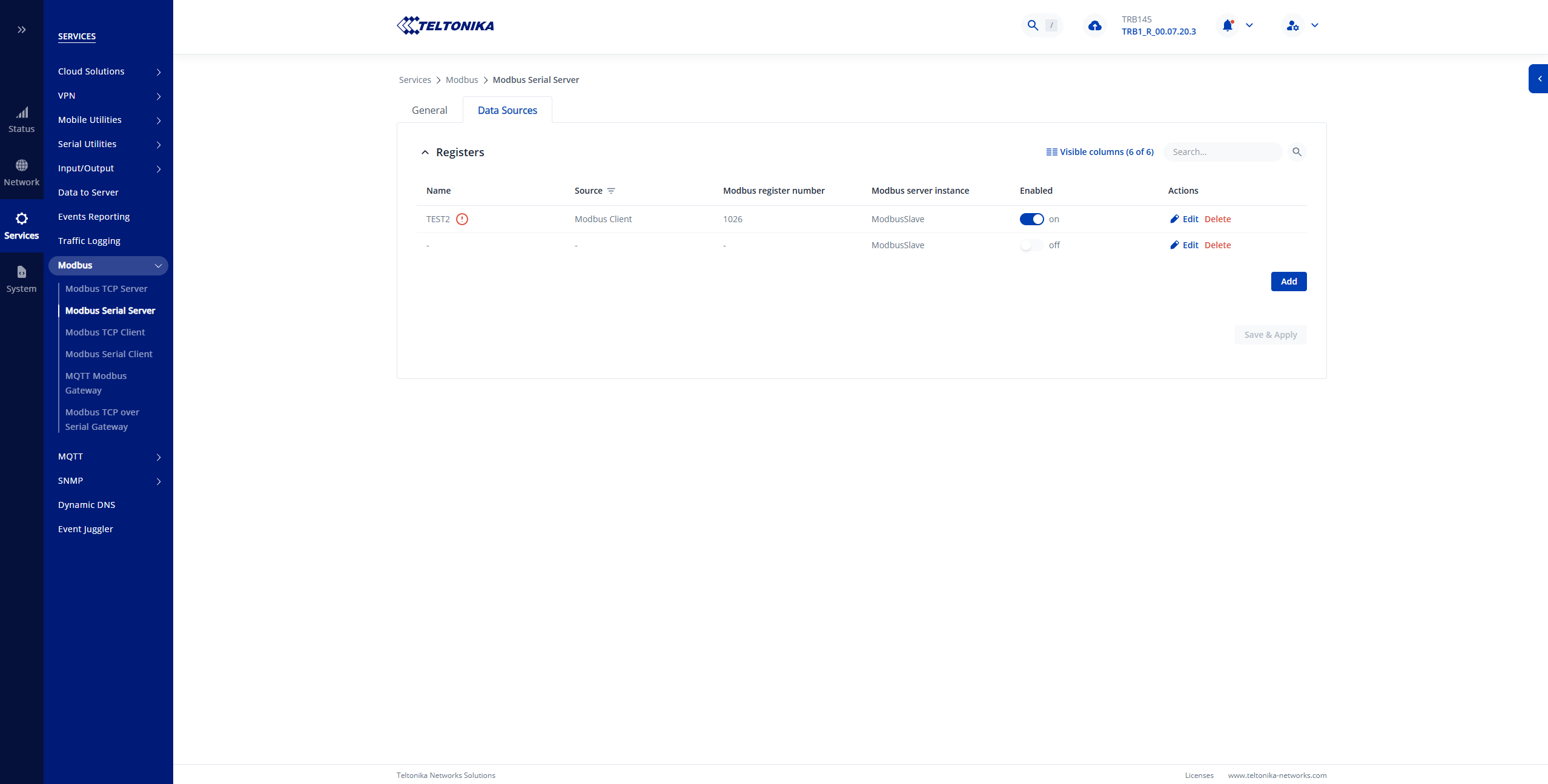
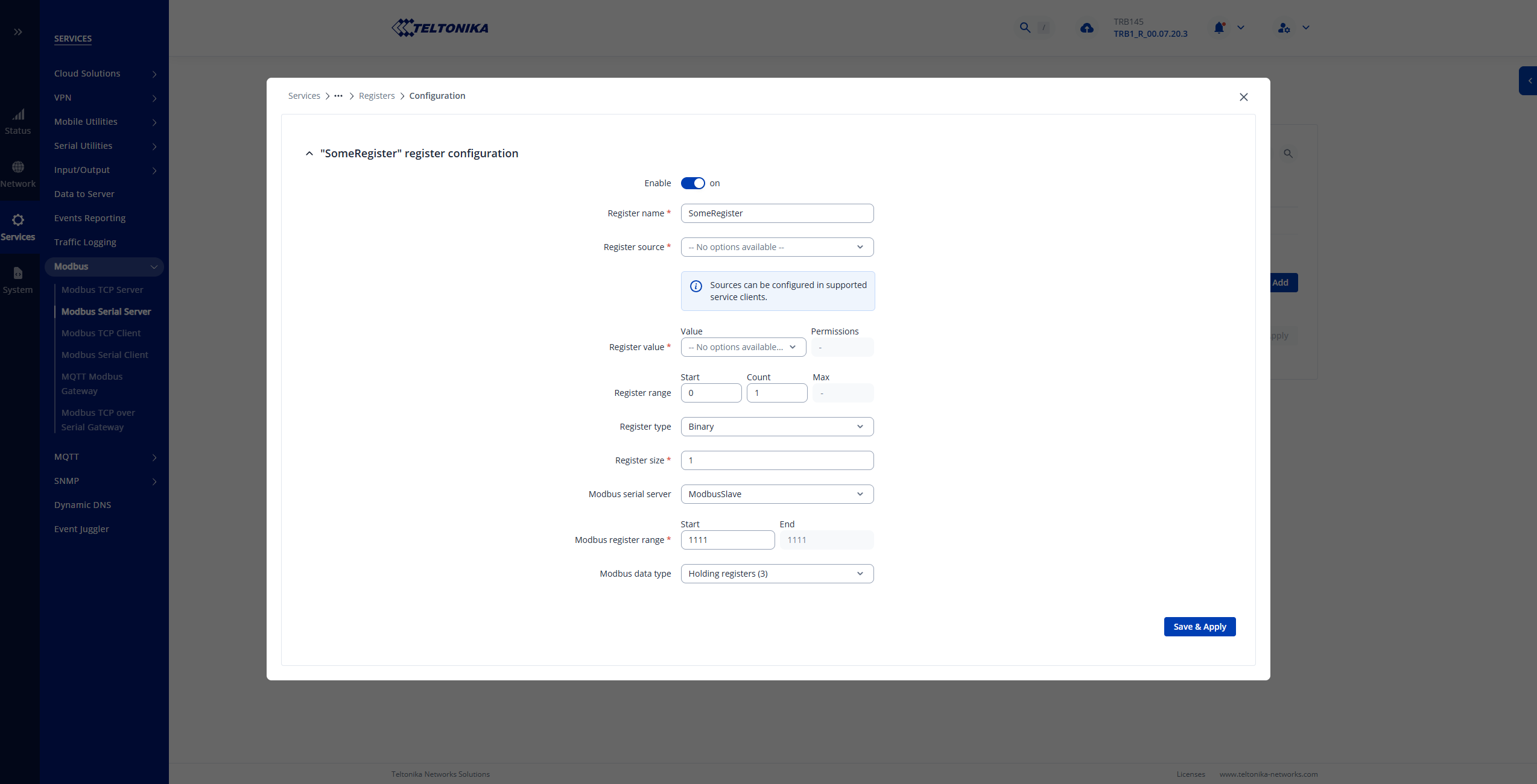
Enable the custom register block.
Example configuration:
Slave ID: 1
Register file:
/tmp/regfile
First register:
1025
Register count:
32
With this configuration, the PLC can write values to the TRB145 register range.
2. PLC Configuration
The PLC should operate as the Modbus RTU Master and write the required value to the TRB145 register.
Example:
Register 1025 = 1
This value change will be detected by the monitoring script.
- Custom Script Logic
A custom shell script running on the TRB145 monitors the configured Modbus register.
The script performs the following actions:
- Periodically reads the Modbus register value.
- Checks whether the configured trigger condition is met.
- Sends an SMS notification using the TRB145 SMS command interface.
- Optionally resets the register value after the SMS has been sent.
Example logic:
WHILE TRUE

    Read Register 1025

    IF Register 1025 = 1 THEN

        Send SMS notification

        Reset Register 1025 to 0

    END IF

END WHILE
This allows the PLC to trigger an SMS alert by writing a specific value to the TRB145 Modbus register.
Important Limitation
The TRB145 cannot operate as both:
- Modbus RTU Client (Master), and
- Modbus RTU Server (Slave)
on the same RS485 interface simultaneously.
The following configuration is not supported:
TRB145 (Modbus RTU Client)
        |
        | RS485
        |
PLC
while also acting as:
External Modbus Master
        |
        | RS485
        |
TRB145 (Modbus RTU Server)
The RS485 interface can only be assigned to one Modbus role at a time.
Therefore, the supported configuration for your application is:
PLC (Modbus RTU Master)
        |
        |
TRB145 (Modbus RTU Slave)
        |
        |
Custom script
        |
        |
SMS notification
During testing, we confirmed the following:
- The TRB145 Modbus Serial Server successfully communicates with a Modbus RTU Master.
- The PLC/Modbus Master can write values to the configured register block.
- The TRB145 register file reflects the written values.
- A custom script can monitor the register value changes.
- The TRB145 SMS functionality can be triggered through the device command interface.
The final script implementation can be adjusted according to the required application logic, including:
- Different trigger register address.
- Different trigger values.
- Multiple alarm conditions.
- Different SMS recipients.
- Register reset behavior after sending the notification.
Please note, that custom script writing is beyond our technical support scope. However, if you have any additional questions, please let me know.
Best regards,
V.