Hello,
We have a RUT906 here and we would like to use the I/O relay to light a 12V DC LED.
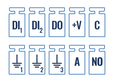
But to be sure that we do not destroy the router, do we need to connect an external power supply (+ DC) to the Common pin 5 and our LED to pin 10 or how should C and NO be connected?
Kind regards
Wim
Hi…
Have you checked here?
https://wiki.teltonika-networks.com/view/RUT906_Input/Output
Maybe you need to build a small circuit to better do what you want…
sample…
Hello,
I already looked at that page, but it’s not clear enough, there is also not an example on the page. It says for pin 5: “Relay Output (COM) (External 0-24 VDC or 0-40 VAC)”. Even though it says output i think i need to power the common pin, but i want to be sure before i give it power and the motherboard gets broken.
Hi…
The I/I port only have around 300mA.
So… you need a “auxiliary circuit”.
" An auxiliary circuit is a circuit that controls, measures, signals, or regulates a main circuit. It is made up of an electrical or mechanical accessory and its wiring. "
Because this… you need a “extra circuit” to increase the power of the I/O ports.
Sample…

So… the I/O just will power up the Q1 and the Q1 will power up the relay… The relay can be connect at 12VDC/120VAC.
and… the I/O will be protect.
Hello,
That is for 1-4 and 6-9, those are input/output? But it says 5 and 10 are for a relay, like a switch for turning on/off the light in a room. So you can connect a device to these pins and control the power to it with the router? Or isn’t that the purpose of these contacts?

Yes… You need to follow your picture to connect the device at RUT.
Hello,
I tested it and it works fine, just wanted to be sure.
Thank you