The other solution may be down the VPN route, I see that the OTD140 has various VPN options available. I would be looking for the SIM data to be as low as possible so we would like to be in control of how often data packets are sent.
Ideally we will have 2 way modbus TCP data between the PLC’s. High speed data transfer is not required, we would be looking to set this to transmit every minute or there abouts.
Yes, you can absolutely read the PLC data. You aren’t stuck with the router’s internal stats; you just point the router’s Modbus client to your PLC’s local IP address. For the lowest data usage, skip the heavy VPNs like OpenVPN. Go with WireGuard or ZeroTier. WireGuard is leaner and won’t “chat” as much in the background, which keeps your SIM costs down. Since you only need to sync every minute, you’re looking at very low data consumption mostly just the overhead of the connection.
If possible, could you please provide a scheme or topology of your network? A simple diagram or description of how the devices are connected would be very helpful for understanding your setup and assisting you more effectively.
Additionally, you mentioned that the end goal is to communicate Modbus data between the two PLCs. Could you please clarify how this communication is intended to work?
For example:
Will one PLC act as a server and the other as a client?
Or will both PLCs send data to the router and then forward it to a remote server?
This information will help clarify the intended architecture and allow me to provide more accurate guidance.
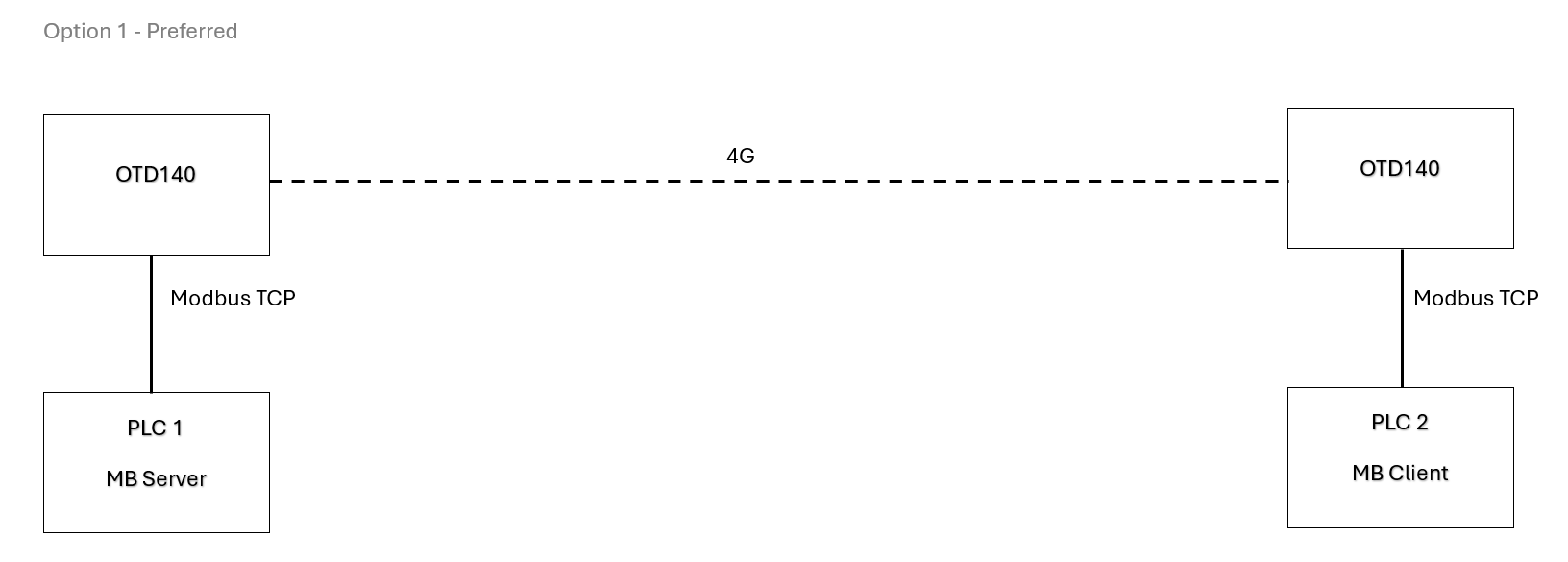
I have attached a simple layout of how I see the final solution working.
Preferably one PLC is the Modbus server and the other is the client.
I have started the config on the OTD140’s and managed to get Modbus comms to/from the PLCs locally so I think our next step is to get a coupe of sim cards with public IP addresses to start testing the 4G side as I don’t see a solution possible without at least one public IP.
Following our discussion on your network topology, here is a step-by-step guide to get both PLCs reporting to the left OTD140 over 4G. The setup involves three phases: IP planning, OpenVPN tunnel, and Modbus client configuration.
IP Address plan:
Before touching any device, you can use these addresses as an example:
Site A (Left)  — OTD140-A
  LAN:          192.168.1.1/24
  PLC 1 IP:     192.168.1.10  (Modbus Server, port 502)
  VPN IP:       10.8.0.1

Site B (Right) — OTD140-B
  LAN:          192.168.2.1/24
  PLC 2 IP:     192.168.2.10  (Modbus Server, port 502)
  VPN IP:       10.8.0.2

VPN Tunnel subnet: 10.8.0.0/30
Public IP: assigned to OTD140-A (Site A)
PLC 2’s default gateway must be set to 192.168.2.1 (OTD140-B’s LAN IP) so return traffic routes correctly through the tunnel.
Generate TLS certificates
Both OTD140s need TLS certificates for a secure OpenVPN tunnel. The easiest way is to generate them directly on OTD140-A.
On OTD140-A WebUI: go to System → Administration → Certificates, click Generate, then go to Certificates Manager and Export the following files:
ca.crt (Certificate Authority)
server.crt + server.key (for OTD140-A)
client.crt + client.key (for OTD140-B)
You can find more information regarding the certificates here:
Configure OpenVPN on OTD140-A (SERVER)**
On OTD140-A WebUI: go to Services → VPN → OpenVPN, click Add, and select Role: Server.
Enable: On
Protocol: UDP
Port: 1194
Tunnel IP: 10.8.0.1
Subnet mask: 255.255.255.252
Authentication: TLS
CA cert: ca.crt
Server cert: server.crt
Server key: server.key
Keepalive: 10 60
Push option: route 192.168.2.0 255.255.255.0
The push route line is critical - it tells the client to route Site B’s LAN through the tunnel so OTD140-A can reach PLC 2.
Under the TLS Clients tab, add OTD140-B:
Common Name: the CN from client.crt
Virtual local endpoint: 10.8.0.1
Virtual remote endpoint: 10.8.0.2
Click Save & Apply.
Configure OpenVPN on OTD140-B (CLIENT)**
On OTD140-B WebUI: go to Services → VPN → OpenVPN, click Add, and select Role: Client.
Enable: On
Protocol: UDP
Remote host: <your public IP>
Port: 1194
Authentication: TLS
CA cert: ca.crt
Client cert: client.crt| Client key: client.key`
Click Save & Apply. After a few seconds the tunnel should show Connected status. Verify by pinging 10.8.0.1 from OTD140-B’s CLI, and 192.168.2.10 (PLC 2) from OTD140-A’s CLI.
Firewall: Allow MODBUS through the tunnel.
On both OTD140s, the OpenVPN zone must be allowed to forward traffic to the LAN zone, otherwise Modbus TCP packets will be dropped.
On each device: Network → Firewall → General Settings → Zones — find the OpenVPN zone and set Forward to LAN. This is a commonly missed step.
Configure MODBUS TCP client on OTD140-A**
First, make sure the Modbus package is installed. On OTD140-A: System → Package Manager — search for Modbus and install if not present.
On OTD140-A WebUI: go to Services → Modbus → Modbus TCP Client, click the Enable toggle to enable the service, then click Add twice - once for each PLC.
Device 1 — PLC 1 (local):
Name: PLC1-SiteA
IP address: 192.168.1.10
Port: 502
Unit ID (Slave ID): 1
Timeout: 3000 ms
Device 2 - PLC 2 (remote, over VPN):
Name: PLC2-SiteB
IP address: 192.168.2.10
Port: 502
Unit ID (Slave ID): 1
Timeout: 5000 ms
Set the timeout for PLC 2 higher (5 seconds) to account for 4G latency. Using the default 500 ms will cause constant false timeouts.
For each device, scroll to Request Configuration and add your polling jobs - set the Register Number, and Register Count to match your PLC’s data map.
For more information please check out these wiki articles:
Verify End-to-End:
Run these checks in order:
VPN tunnel up? → Services → VPN → OpenVPN on OTD140-A should show client as Connected.
Can reach PLC 2 through tunnel? → On OTD140-A CLI: ping 192.168.2.10
Modbus polling working? → In each Request Configuration, use the built-in Test button - it sends a live Modbus read and shows the response value inline.
Firewall blocking anything? → Check Firewall logs on both devices if any step above fails.
Once everything is up you’ll have all of PLC 1 and PLC 2’s registers polled and stored on OTD140-A, ready for whatever you decide to do next - MQTT forwarding, Data to Server, local logging, etc. Let me know if you face any difficulties at any of the phases.
I am keen to try this out but I believe I need to get at least 1 public static IP address for this to work. Is this correct?
We are struggling to find readily available sim cards that provide this and seems to be getting tricky to find ISP’s that are supporting public static IP’s now.
Since it is difficult to acquire a public IP address from your ISP, here are a few alternatives:
Teltonika RMS (VPN / Connect)
Cloud-based solution from Teltonika Networks. Devices establish outbound connections to RMS, allowing secure remote access and inter-device connectivity even behind carrier NAT.
WireGuard (with Relay/VPS)
Both routers initiate outbound connections to a cloud VPS acting as a hub. No public IP needed on either site, only on the VPS.
ZeroTier
Encrypted overlay network where both devices join the same virtual network. Works behind NAT without requiring public IP addresses.
These options allow secure Modbus TCP communication without exposing either site directly to the internet.