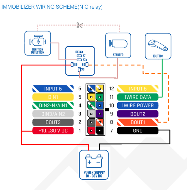
Relay wiring with a teletonika fmb920 device,ignition,sarter and power supply
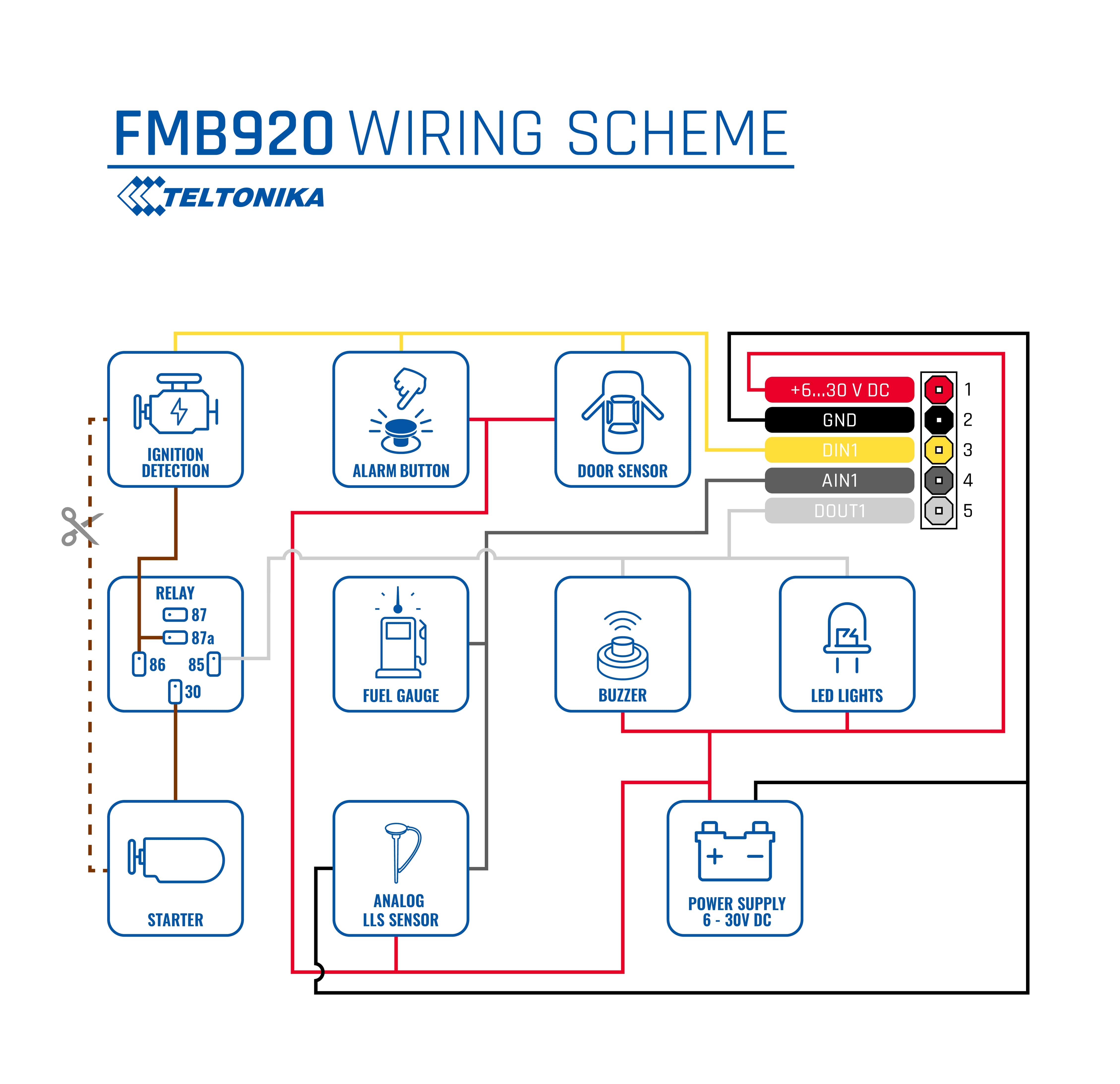
Good day, please check this schemes: Wiring-scheme-FMB920.jpg (4517×4370) (teltonika-gps.com)
Best Regards
Maynard C.
1 Like
I followed the scheme very well but when i block the vehicle engine on the platform the buld that act as my starter its not going off
kindly find the attached screenshot,
Kindly provide the details of the installation process and how it was done on your side. There might be something in the installation that caused it not to work. If you explain your concept and what exactly was done from your side, it will help clarify the situation from our end.
Best regards,
Amalnath.


Dear @Ignatius_GoodSamarit,
Good day!
Kindly provide details about the relay pins that you connected, as the picture does not clearly show which pins are used.
Kind regards,
Amalnath.
Good day I am having the same issue but on firmware 3.27XXX going up. Firmware 3.25XX works well
HHi @Delah
Did you try using 03.29.XX.XX firmware?
If you have any issues regarding DOUT please get in touch with your sales manager or create an HD ticket.
If you don’t have any contacts with our Sales managers, please get in touch with them on our official website https://teltonika-gps.com/ and click on the “Contact Us” button. When you click, please fill out the form and submit it.
Best Regards
Maynard C
1 Like
One wire from the bulb(starter) is connected to negative wire from power supply, another bulb wire is connected to 87a on a relay. And one wire of the switch(ignition) is connected to positive wire from a power supply then connected to 30 on relay, another switch wire is connected to negative wire from from the power supply. 86 on relay is connected to positive power supply and 85 to Dout1(white)
This topic was automatically closed after 5 days. New replies are no longer allowed.